


Separator Sizing
Here we review important guidelines and procedures for sizing multiphase separators:
General Guidelines
Droplet Settling Theory
Liquid Retention Time
Sizing Procedure
Improvements Offered by CFD Simulations
General Guidelines
Orientation
For
practical
design
of
separators,
it
is
necessary
to
compare
both
horizontal
and
vertical
orientation
designs
to
determine
which
design
is
more
economical
(Svrcek
and
Monnery,
1993).
However,
the
following
general
guidelines
are
recommended
to
be
considered
while
sizing
multiphase separators.
Vertical orientation
advantages
:
•
Occupy little plot space
•
Easier than horizontal separators to transport and install
•
Used
when
there
is
small
liquid
load,
limited
plot
space,
or
where
ease
of
level
control
is
desired (Evans, 1974)
•
Preferred for operating either low or very high gas/oil ratio fluids (Arnold and Stewart, 2008)
Horizontal orientation
advantages
:
•
Higher operating capacity, and processing capabilities
•
Preferred
when
emulsions,
foam,
or
high
gas/oil
ratio
fluids
are
present
(Arnold
and
Stewart,
2008)
Separator Aspect Ratio (Length/Diameter)
Plot restrictions and economic measures specify the separator aspect ratio. Different ranges have
been suggested as shown in the table below
Economic
studies
provided
the
separator
aspect
ratio
as
a
function
of
the
operating
pressure
(Walas, 1990; Svrcek and Monnery, 1993). The recommended values presented in the table
.
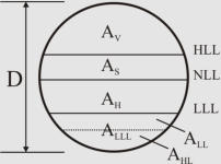
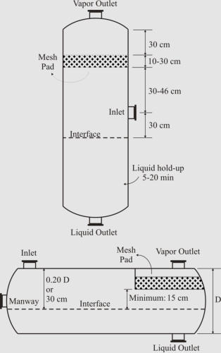
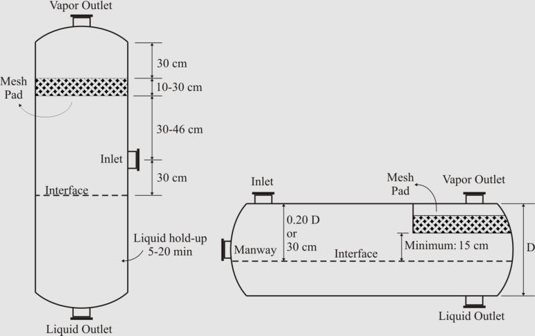
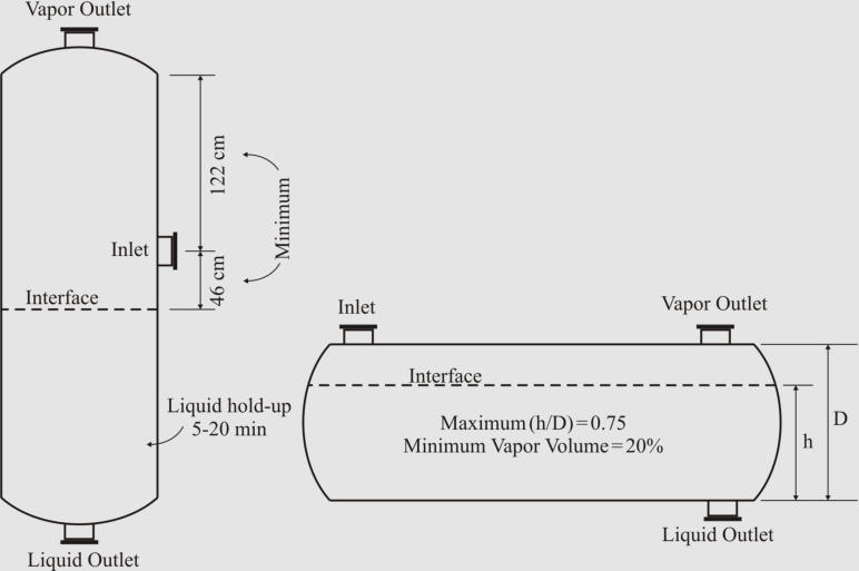
The
figures
below
show
illustrated
guidelines
proposed
by
Walas
(1990)
and
Watkins
(1967)
for
two-phase separators with and without demisters, respectively.
Design Heuristics Proposed by Walas (1990) for Two-Phase Separators Equipped with Wire Mesh
Demisters.
Design Heuristics Proposed by Watkins (1967) for Two-Phase Separators.
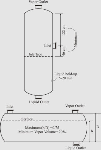
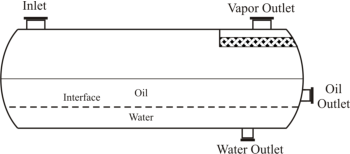
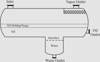
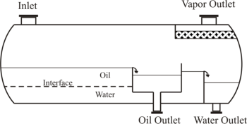
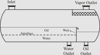
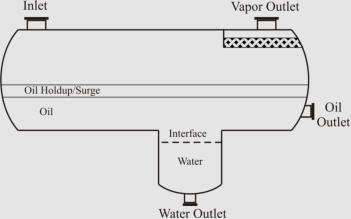
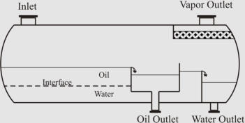
There
are
also
some
general
guidelines
for
choosing
among
different
horizontal
separators
(see
the
figure
below)
which
are
worth
mentioning:
As
per
Arnold
and
Stewart
(2008),
while
the
simple
design
is
easily
adjustable
to
handle
unexpected
changes
in
liquid
density/flow
rates,
the
bucket
&
weir
design
is
used
when
interface
level
control
is
difficult
(emulsions
or
paraffin
problems).
If
heavy
liquid
mass
fraction
is
substantial,
the
weir
design
is
preferable,
but
the
boot
design is preferred when heavy liquid mass fraction is less than 20% (Monnery and Svrcek, 1994).
(
a
)
(
b)
(
c) (
d)
Different Common Designs of Horizontal Three-Phase Separators; (a) “Simple”, (b) “Boot”, (c)
“Weir”, and (d) “Bucket and Weir”.
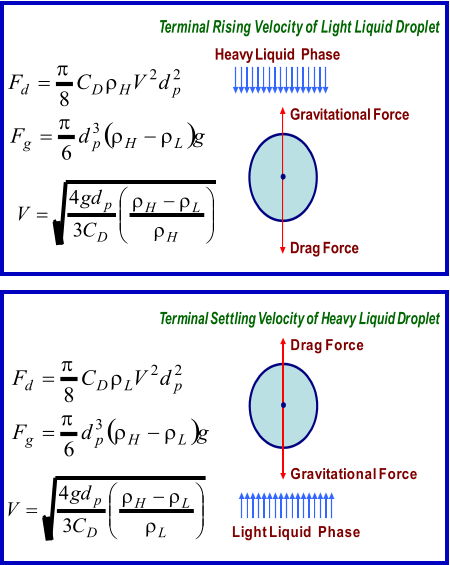
Droplet Settling Theory
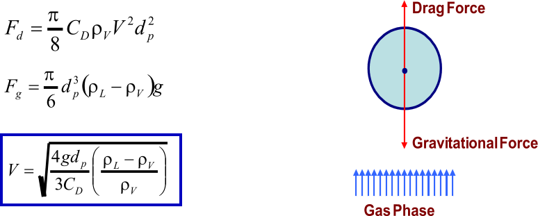
Liquid Droplet in Vapor Phase
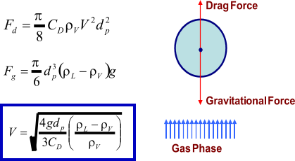
The
force
balance
between
drag
and
gravitational
forces
exerted
on
a
liquid
droplet
leads
to
its
terminal settling velocity
:
Drag
coefficient
for
vapor-liquid
separation
can
be
obtained
from
the
diagram
proposed
by
GPSA.
This
diagram
is
applicable
if
Re
p
is
between
0.4
and
1500.
The
diagram
curve
can
be
regressed as shown in the following with SI units (Monnery and Svrcek, 2000)
:
As
presented
in
the
table,
there
are
different
values
recommended
by
the
field
researchers
for
the
design droplet size
.
In
separator
sizing
literature,
it
is
very
common
to
rearrange
the
settling
velocity
equation
introducing
a
K
coefficient,
known
as
the
settling
velocity
coefficient.
This
leads
to
the
Sauders-
Brown equatio
n:
Different
values
are
suggested
in
the
literature
to
be
used
for
the
settling
velocity
coefficient.
The
following table provides some of these suggestion
s:
More
sophisticated
approaches
recommend
that
pressure
functionality
need
be
considered
for
the
settling
velocity
coefficient.
The
approaches
proposed
by
York
Mist
Eliminator
Company
and
GPSA are given at below (Svrcek and Monnery, 1993):
York Mist Eliminator Compan
y
GPS
A
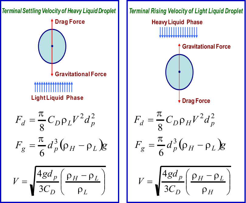
Liquid Droplet in Liquid Phase
Similar
to
vapor-liquid
separation,
the
force
balance
between
drag
and
gravitational
forces
exerted on a liquid droplet leads to its terminal velocity
:
It
is
generally
assumed
that
Re
p
is
lower
than
0.1
and
Stokes’
law
can
be
used
for
calculating
the
drag coefficient: C
D
= 24/Re
p
This assumption results in a very simple equation for the liquid droplet terminal velocit
y:
Some design droplet sizes recommended in the literature are shown in the tabl
e.
Liquid Retention Time
In
order
to
handle
upstream
or
downstream
variations
and
establish
smooth
and
safe
operation
of
downstream
facilities,
an
adequate
liquid
retention
time
need
be
assumed.
This
assumption
may
be
based
on
experience,
scale
model
predictions,
or
field
data.
Liquid
retention
time
is
combined
from
holdup
and
surge
time.
Holdup,
considered
for
smooth
and
safe
operation
of
downstream
facilities,
is
defined
as
the
time
it
takes
to
reduce
the
liquid
level
from
normal
to
low
liquid
level
by
closing
inlet
flow
while
maintaining
a
normal
outlet
flow.
Surge
time,
considered
for
handling
upstream
or
downstream
variations,
is
defined
as
the
time
it
takes
to
increase
the
liquid
level
from
normal
to
high
liquid
level
by
closing
outlet
flow
while
maintaining
a
normal
inlet
flow.
Some
rules-of-thumb
have
been
suggested
at
literature
which
are
not
in
reasonable
agreement
with each other as shown in the table
.
In
the
more
pragmatic
approach
presented
by
Svrcek
and
Monnery
in
1993
and
1994,
low
liquid
level
is
first
set
based
on
the
operating
pressure
and
diameter
(typical:
6-12
in).
Then,
holdup
(typical:
2-10
min)
and
surge
times
(typical:
1-5
min)
are
specified
based
on
the
service
and
quality
of the personnel and instrumentation (with impact factor of 1.0 – 1.5 altogether).
Sizing Procedure
The
sizing
approach
outlined
here
is
proposed
by
Svrcek
and
Monnery
through
two
internationally
acclaimed
papers
in
1993
and
1994.
It
is
an
algorithmic
method
for
designing
the
most
economical
separator.
Among
the
classic
methods,
the
method
offers
the
most
comprehensive
approach
while
benefiting
from
the
accepted
industrial
design
guidelines.
As
explained
in
the
following,
height
adjustments
are
made
for
sizing
vertical
separators
and
iterative calculations are performed for finding the most economical horizontal separator.
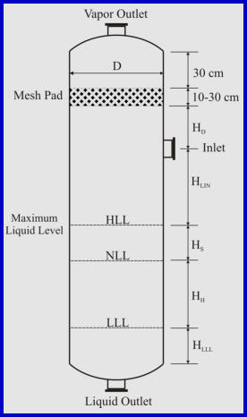
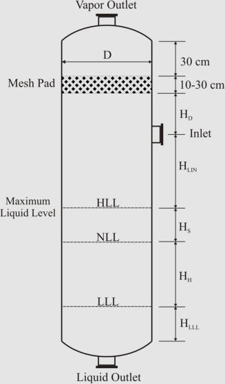
Sizing Vertical Two-Phase Separat
o
r
1. Calculate the terminal settling velocity of liquid droplets.
2. Set the vapor velocity equal to 75% of the terminal
settling velocity.
3. Calculate the vessel diameter based on the vapor
volumetric flow-rate and the vapor velocity.
4. Obtain low liquid level height (typical: 6-12 in).
5. Calculate the height from LLL to NLL based on the
required holdup time (typical: 2-10 min).
6. Calculate the height from NLL to HLL based on the
surge time (typical: 1-5 min).
7. Calculate the height from HLL to the inlet nozzle
centerline based on the inlet nozzle size which can be
calculated as:
8. Assume the disengagement height (H
D
) to be about
0.5D (Min: 42 in or 30 in with demister).
9. Calculate the vessel height. If the aspect ratio is not
in the range of 1.5-6.0, increase the diameter (to
decrease the aspect ratio) or increase vapor
disengagement height (to increase the aspect ratio) and
fix the problem.
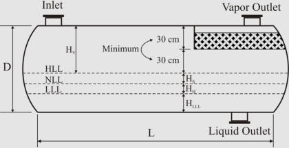
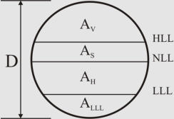
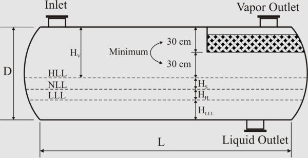
Sizing Horizontal Two-Phase Separat
or
In
horizontal
arrangement,
cross-sectional
area
of
the
vessel
is
shared
by
vapor-liquid
disengagement
area
and
areas
for
liquid
retention and low liquid level.
Here is the iterative algorithmic method for sizing:
1. Calculate the terminal settling velocity of liquid droplets. Use
0.75U
T
as the settling velocity (25% contingency).
2. Calculate the holdup volume based on the required holdup
time (typical: 2-10 min) and liquid volumetric flow rate.
3. Calculate the surge volume based on the surge time (typical: 1-5 min) and liquid volumetric
flow rate.
4. Assume an aspect ratio (L/D) based on the operating pressure and calculate an initial diameter:
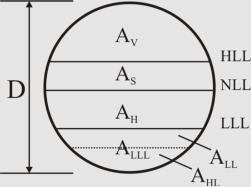
5. Obtain LLL (typical: 6-12 in) and calculate A
LLL
.
6. Set H
V
to the larger of 0.2D or 1 ft (no demister), 2 ft (with demister). Calculate A
V
.
7. Calculate L to accommodate the liquid retention volume: L = (V
H
+V
S
)/(A
T
-A
V
-A
LLL
)
8. Calculate the minimum length required for vapor-liquid separation: L
min
= (Q
V
/A
V
)(H
V
/U
T
)
9. If L < 0.8L
min
, increase H
V
and go to step 7. Else if L < L
min
, set L = L
min
. Else if L > 1.2L
min
,
decrease H
V
(if acceptable), and go to step 7. Else (L > L
min
), L is acceptable.
10. If L/D < 1.5, decrease D and go to step 5. Else if L/D > 6, increase D and go to step 5.
11. Calculate the approximate vessel weight based on the thickness and surface area of shell and
heads.
12. In order to find the optimum case (the minimum weight), change the vessel diameter by 6 in
increments and repeat the calculations from step 5 while keeping the aspect ratio in the range of
1.5 to 6.0.
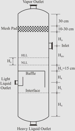
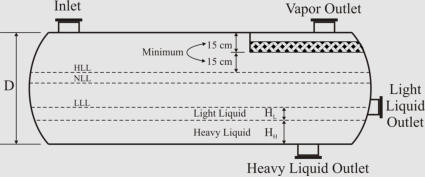
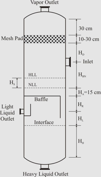
Sizing Vertical Three-Phase Separator
1. Calculate the terminal settling velocity of light liquid droplets.
2. Set the vapor velocity equal to 75% of the terminal settling velocity.
3. Calculate the vessel diameter based on the vapor
volumetric flow-rate and the vapor velocity.
4. Calculate the separation velocities of both liquid
phases through each other.
5. Set the thickness of liquid phases (HLL = HHL =
0.3 m as minimum), and calculate the separation
times for the liquid droplets (t
HL
and t
LH
).
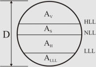
6. Calculate the cross-sectional areas of the liquid
phases. Note, A
H
is the same as the vessel cross-
sectional area (A
H
= A), but the area allotted to baffle
plate down-comer should be subtracted from A to
obtain A
L
.
7. Calculate the residence time of the light liquid:
t
RL
= H
L
A
L
/Q
LL
. If t
RL
< t
HL
increase the vessel diameter
so that t
RL
= t
HL
.
8. Calculate the residence time of the heavy liquid:
t
RH
= H
H
A
H
/Q
HL
. If t
RH
< t
LH
increase the vessel
diameter so that t
RH
= t
LH
.
9. Calculate the height of light liquid phase above the
outlet (H
R
) based on the required holdup time
(typical: 2-10 min) and liquid flow rate.
10. Calculate the surge height (H
S
) based on the surge time (typical: 1-5 min) and liquid flow rate.
11. Set liquid level above baffle (H
A
= 0.15 m minimum).
12. Calculate the height from NLL to the inlet nozzle centerline based on the surge height (H
S
) and
the inlet nozzle size which can be calculated as:
13. Assume the disengagement height (H
D
) to be about 0.5D (minimum: 24”+0.5d
N
with demister
or 36”+0.5d
N
no demister).
14. Calculate the vessel height. If the aspect ratio is not in the range of 1.5-6.0, increase the
diameter (to decrease the aspect ratio) or height (to increase the aspect ratio) of the separator and
fix the problem.
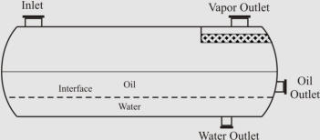
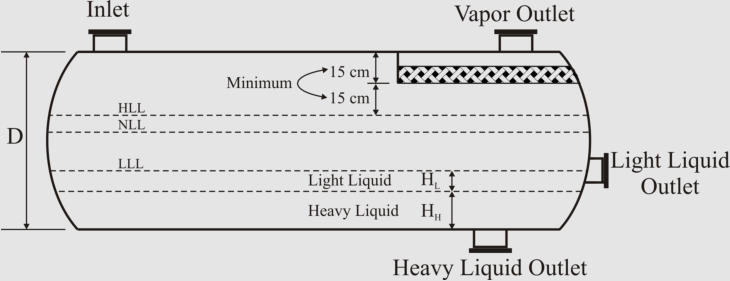
Sizing Horizontal Three-Phase Separator
In
order
to
show
the
sizing
strategy,
only
“simple”
horizontal
separator
is
presented
here.
The
other
arrangements,
i.e.
“weir”,
“boot”,
and
“bucket
&
weir”,
follow
the
same
strategy
but
require
further effort for sizing their compartments.
In
horizontal
arrangement,
cross-se
c
tional
area
of
the
vessel
is
shared
by
vapor-liquid
disengagement
area
and
areas
for
liquid
retention
and
low
liquid level. Here is the iterative algorithmic method for sizing:
1. Calculate the terminal settling velocity of light liquid
droplets. Use 0.75U
T
as the settling velocity (25% contingency).
2. Calculate the holdup volume based on the required holdup
time (typical: 2-10 min) and liquid volumetric flow rate.
3. Calculate the surge volume based on the surge time (typical:
1-5 min) and liquid volumetric flow rate.
4. Assume an aspect ratio (L/D) based on the operating pressure and calculate an initial diameter:
5. Set the thickness of liquid phases (minimum: HLL = HHL = 0.3 m), and calculate A
LLL
= A
HL
+A
LL
.
6. Set H
V
to the larger of 0.2D or 1 ft (no demister), 2 ft (with demister). Calculate A
V
.
7. Calculate L to accommodate the liquid retention volume: L = (V
H
+V
S
)/(A
T
-A
V
-A
LLL
)
8. Calculate the minimum length required for vapor-liquid separation: L
min
= (Q
V
/A
V
)(H
V
/U
T
)
9. If L < 0.8L
min
, increase H
V
and go to step 7. Else if L < L
min
, set L = L
min
. Else if L > 1.2L
min
,
decrease H
V
(if acceptable), and go to step 7. Else (L > L
min
), L is acceptable.
10. Calculate the liquid-liquid separation times: t
HL
= (D-H
V
-HHL)/U
HL
and t
LH
= HHL/U
LH
11. Calculate the light liquid residence time: t
RL
= L(A-A
V
-A
HL
)/Q
LL
.
If t
RL
< t
HL
increase L so that t
RL
= t
HL
.
12. Calculate the heavy liquid residence time: t
RH
= LA
HL
/Q
HL
.
If t
RH
< t
LH
increase L so that t
RH
= t
LH
.
13. If L/D < 1.5, decrease D (if acceptable) and go to step 5. Else if L/D > 6, increase D and go to step
5.
14. Calculate the approximate vessel weight based on thickness and surface area of shell and
heads.
15. In order to find the optimum case (the minimum weight), change the vessel diameter by 6”
increments, and repeat the calculations from step 5 while keeping the aspect ratio in the range of
1.5 to 6.0.
Improvements Offered by CFD Simulations
We
have
recently
developed
Computational
Fluid
Dynamics
(CFD)
based
simulation
of
multiphase
separators.
In
order
to
study
selected
aspects
of
phase
separation,
the
focus
was
placed
on
hydrocarbon-water
systems,
and
the
oilfield
separator
data
ranging
from
light
oil
conditions
to
heavy
oil
conditions
were
used
in
these
multiphase
separator
simulations.
An
efficient
combination
of
two
multiphase
simulation
models
available,
VOF
and
DPM,
with
appropriate
model
assumptions
and
settings
was
used.
Two
independent
sets
of
CFD
simulations,
one
for
vapor-liquid
separation
and
the
other
for
liquid-liquid
separation,
were
performed
using
simple
and efficient grid systems.
When
compared
to
classic
design
strategies,
CFD
simulations
indicated
that
additional
residence
times
are
necessary
for
droplets
to
pass
through
the
interfaces.
The
interface
residence
time
may
be as high as around 100 s depending on the fluid properties.
In
the
vapor-liquid
separation
compartment,
the
efficient
droplet
size
and
the
appropriate
extra
vapor
residence
time
(for
droplet
penetration
through
the
interface)
were
estimated
as
a
function
of
the
vapor
density.
It
was
shown
that
for
the
three-phase
separator
case
study,
the
efficient
separation
of
oil
droplets
from
gas
phase
results
in
total
separation
of
water
droplets
from
the
gas
phase.
For
the
liquid-liquid
separation
process,
the
upper
limit
of
Stokes’
law
(Re
p
<
0.1)
was
exceeded
in
several case studies. Hence, Abraham equation (Re
p
< 2000) was recommended to be used inste
ad:
Using
the
Abraham
equation
in
liquid-liquid
separation
calculations,
the
efficient
droplet
size
was
estimated
based
on
continuous
phase
viscosity.
Hence,
for
water
droplets,
a
linear
regression
fit
based
on
the
oil
phase
viscosity
was
developed.
An
oil
droplet
size
of
around
600
micron
can
be
assumed
if
the
Abraham
equation
is
used
for
estimation
of
the
rising
velocity
of
oil
droplets
out
of
the
water
phase.
Furthermore,
it
was
shown
that
the
use
of
Stokes’
law
for
interpretation
of
CFD
results
does
lead
to
a
weak
correlation
between
efficient
droplet
sizes
and
continuous
phase
viscosities.
A
comprehensive
CFD-based
study
on
the
velocity
constraints
caused
by
re-entrainment
in
horizontal
separators
confirmed
that,
as
per
practical
experience,
high
vapor
densities
and
high
oil
viscosities reduce the maximum safe velocity of the vapor phase.
The
results
of
CFD
simulations,
using
all
the
feasible
horizontal
designs
and
selected
oilfield
conditions,
indicated
that
the
oil
phase
does
not
re-entrain
the
water
droplets,
but
the
oil
droplets
may
be
“re-entrained”
by
the
water
phase
at
a
high
velocity.
It
was
also
elucidated
that
the
geometry
of
water
phase
compartment
in
horizontal
separators
is
a
key
factor
affecting
the
liquid-
liquid
re-entrainment
phenomenon.
The
maximum
safe
cross-sectional
velocity
of
the
water
phase
was a linear function of the oil viscosity.
Finally,
it
was
shown
that
the
algorithmic
design
method
of
Monnery
and
Svrcek
(1994)
can
be
modified
to
use
CFD
simulation
results
to
specify
a
realistic
optimum
separator
design/size.
This
fact
was
elaborated
through
the
mobile/desktop
applications
developed
for
sizing
two-phase
and
three-phase separators. Please click
here
for more information.
The
serious
process
engineers
can
download
a
complete
and
colourful
version
of
this
interesting
PhD thesis from
here
to acquire more details on practical sizing formula.
References:
Abraham, F.F., “Functional Dependence of Drag Coefficient of a Sphere on Reynolds Number”,
Physics of Fluids, 13, 1970, 2194-2195.
Arnold, K., Stewart, M., “Surface Production Operations”, 3
rd
Edition, Elsevier, 2008.
Branan, C., “The Process Engineers Pocket Handbook”, Vol. 2, Gulf, 1983.
Evans, F.L., “Equipment Design Handbook for Refineries and Chemical Plants”, Vol. 2, Gulf,
1974.
Gas Processors Suppliers Association, GPSA Engineering Data Book, 11
th
Edition, Vol. 1, Gas
Processors Association, 1998.
Gerunda, A., “How to Size Liquid-Vapor Separators”, Chemical Engineering, May 4, 1981, 81-84.
Hooper, W.B., “Decantation”, Section 1.11 in “Handbook of Separation Techniques for Chemical
Engineers”, Ph.A. Schweitzer (Ed.), 3
rd
Edition, McGraw-Hill, 1997.
Lyons, W.C., Plisga, G.J. (Editors), “Standard Handbook of Petroleum and Natural Gas
Engineering”, Volume 2, Gulf Professional Publishing, 2005.
Monnery, W.D., Svrcek, W.Y., “Analytical Study of Liquid/Vapor Separation Efficiency”, PTAC,
2000.
Monnery, W.D., Svrcek, W.Y., “Successfully Specify Three-Phase Separators”, Chem. Eng.
Progress, September, 1994, 29-40.
Pourahmadi Laleh, A., "CFD Simulation of Multiphase Separators", PhD Thesis, University of
Calgary, Calgary, Canada, 2010.
Pourahmadi Laleh, A., Svrcek, W.Y., Monnery, W.D., "CFD Simulation of Oilfield Separators: A
Realistic Approach", LAMBERT Academic Publishing, 2011.
Sinnott, R.K., “Chemical Engineering Design” in “Coulson & Richardson’s Chemical
Engineering”, 2
nd
Edition, Butterworth-Heinemann, 1997.
Smith, H.V., “Oil and Gas Separators”, in “Petroleum Engineering Handbook”, Bradley, H.B. (Ed),
Society of Petroleum Engineers, 1987.
Stokes, G.G., “On the Theories of Internal Friction of Fluids in Motion, and of the Equilibrium
and Motion of Elastic Solids”, Transaction of the Cambridge Philosophical Society, 8(22), 1845,
287-305.
Svrcek, W.Y. and W.D. Monnery, "Design Two-Phase Separators within the Right Limits", Chem.
Eng. Prog. 89(10), 53-60, 1993.
Walas, S.M., “Process Vessels”, Chapter 18 in “Chemical Process Equipment Selection and
Design”, Butterworth-Heinemann, 1990.
Watkins, R.N., “Sizing Separators and Accumulators”, Hydrocarbon Proc., 46(11), 1967.
Wu, F.H., “Separators, Liquid-Vapor, Drum Design”, in “Encyclopedia of Chemical Processing
and Design”, J.J. McKetta, W.A. Cunningham (Ed.), Marcel Dekker, 1990.


Separator Sizing
Here we review important guidelines and procedures for
sizing multiphase separators:
General Guidelines
Droplet Settling Theory
Liquid Retention Time
Sizing Procedure
Improvements Offered by CFD Simulations
General Guidelines
Orientation
For
practical
design
of
separators,
it
is
necessary
to
compare
both
horizontal
and
vertical
orientation
designs
to
determine
which
design
is
more
economical
(Svrcek
and
Monnery,
1993).
However,
the
following
general
guidelines
are
recommended
to
be
considered
while
sizing
multiphase
separators.
Vertical orientation
advantages
:
•
Occupy little plot space
•
Easier
than
horizontal
separators
to
transport
and
install
•
Used
when
there
is
small
liquid
load,
limited
plot
space,
or
where
ease
of
level
control
is
desired
(Evans,
1974)
•
Preferred
for
operating
either
low
or
very
high
gas/oil
ratio fluids (Arnold and Stewart, 2008)
Horizontal orientation
advantages
:
•
Higher operating capacity, and processing capabilities
•
Preferred
when
emulsions,
foam,
or
high
gas/oil
ratio
fluids are present (Arnold and Stewart, 2008)
Separator Aspect Ratio (Length/Diameter)
Plot restrictions and economic measures specify the
separator aspect ratio. Different ranges have been suggested
as shown in the table below
Economic
studies
provided
the
separator
aspect
ratio
as
a
function
of
the
operating
pressure
(Walas,
1990;
Svrcek
and
Monnery,
1993).
The
recommended
values
presented
in
the
table
.
The
figures
below
show
illustrated
guidelines
proposed
by
Walas
(1990)
and
Watkins
(1967)
for
two-phase
separators
with and without demisters, respectively.
Design Heuristics Proposed by Walas (1990) for Two-Phase
Separators Equipped with Wire Mesh Demisters.
Design Heuristics Proposed by Watkins (1967) for Two-
Phase Separators.
There
are
also
some
general
guidelines
for
choosing
among
different
horizontal
separators
(see
the
figure
below)
which
are
worth
mentioning:
As
per
Arnold
and
Stewart
(2008),
while
the
simple
design
is
easily
adjustable
to
handle
unexpected
changes
in
liquid
density/flow
rates,
the
bucket
&
weir
design
is
used
when
interface
level
control
is
difficult
(emulsions
or
paraffin
problems).
If
heavy
liquid
mass
fraction
is
substantial,
the
weir
design
is
preferable,
but
the
boot
design
is
preferred
when
heavy
liquid
mass
fraction is less than 20% (Monnery and Svrcek, 1994)
.
(a)
(b)
( c )
(d)
Different Common Designs of Horizontal Three-Phase
Separators; (a) “Simple”, (b) “Boot”, (c) “Weir”, and (d)
“Bucket and Weir”.
Droplet Settling Theory
Liquid Droplet in Vapor Phase
The
force
balance
between
drag
and
gravitational
forces
exerted
on
a
liquid
droplet
leads
to
its
terminal
settling
velocit
y:
Drag
coefficient
for
vapor-liquid
separation
can
be
obtained
from
the
diagram
proposed
by
GPSA.
This
diagram
is
applicable
if
Re
p
is
between
0.4
and
1500.
The
diagram
curve
can
be
regressed
as
shown
in
the
following
with
SI
units
(Monnery and Svrcek, 2000)
:
As
presented
in
the
table,
there
are
different
values
recommended
by
the
field
researchers
for
the
design
droplet
size
.
In
separator
sizing
literature,
it
is
very
common
to
rearrange
the
settling
velocity
equation
introducing
a
K
coefficient,
known
as
the
settling
velocity
coefficient.
This
leads
to
the
Sauders-Brown equation
:
Different
values
are
suggested
in
the
literature
to
be
used
for
the
settling
velocity
coefficient.
The
following
table
provides some of these suggestions
:
More
sophisticated
approaches
recommend
that
pressure
functionality
need
be
considered
for
the
settling
velocity
coefficient.
The
approaches
proposed
by
York
Mist
Eliminator
Company
and
GPSA
are
given
at
below
(Svrcek
and Monnery, 1993):
York Mist Eliminator Compan
y
GPS
A
Liquid Droplet in Liquid Phase
Similar
to
vapor-liquid
separation,
the
force
balance
between
drag
and
gravitational
forces
exerted
on
a
liquid
droplet leads to its terminal velocity
:
It
is
generally
assumed
that
Re
p
is
lower
than
0.1
and
Stokes’
law can be used for calculating the drag coefficient:
C
D
= 24/Re
p
This
assumption
results
in
a
very
simple
equation
for
the
liquid droplet terminal velocity
:
Some
design
droplet
sizes
recommended
in
the
literature
are
shown in the tabl
e.
Liquid Retention Time
In
order
to
handle
upstream
or
downstream
variations
and
establish
smooth
and
safe
operation
of
downstream
facilities,
an
adequate
liquid
retention
time
need
be
assumed.
This
assumption
may
be
based
on
experience,
scale
model
predictions,
or
field
data.
Liquid
retention
time
is
combined
from
holdup
and
surge
time.
Holdup,
considered
for
smooth
and
safe
operation
of
downstream
facilities,
is
defined
as
the
time
it
takes
to
reduce
the
liquid
level
from
normal
to
low
liquid
level
by
closing
inlet
flow
while
maintaining
a
normal
outlet
flow.
Surge
time,
considered
for
handling
upstream
or
downstream
variations,
is
defined
as
the
time
it
takes
to
increase
the
liquid
level
from
normal
to
high
liquid
level
by
closing
outlet
flow
while
maintaining
a
normal
inlet
flow.
Some
rules-of-
thumb
have
been
suggested
at
literature
which
are
not
in
reasonable agreement with each other as shown in the table
.
In
the
more
pragmatic
approach
presented
by
Svrcek
and
Monnery
in
1993
and
1994,
low
liquid
level
is
first
set
based
on
the
operating
pressure
and
diameter
(typical:
6-12
in).
Then,
holdup
(typical:
2-10
min)
and
surge
times
(typical:
1-5
min)
are
specified
based
on
the
service
and
quality
of
the
personnel
and
instrumentation
(with
impact
factor
of
1.0
–
1.5 altogether).
Sizing Procedure
The
sizing
approach
outlined
here
is
proposed
by
Svrcek
and
Monnery
through
two
internationally
acclaimed
papers
in
1993
and
1994.
It
is
an
algorithmic
method
for
designing
the
most
economical
separator.
Among
the
classic
methods,
the
method
offers
the
most
comprehensive
approach
while
benefiting
from
the
accepted
industrial
design
guidelines.
As
explained
in
the
following,
height
adjustments
are
made
for
sizing
vertical
separators
and
iterative
calculations
are
performed
for
finding
the
most
economical
horizontal
separator.
Sizing Vertical Two-Phase Separat
or
1. Calculate the
terminal settling
velocity of liquid
droplets.
2. Set the vapor
velocity equal to 75%
of the terminal
settling velocity.
3. Calculate the vessel
diameter based on the
vapor volumetric
flow-rate and the
vapor velocity.
4. Obtain low liquid
level height (typical:
6-12 in).
5. Calculate the height
from LLL to NLL
based on the required
holdup time (typical:
2-10 min).
6. Calculate the height
from NLL to HLL based on the surge time (typical: 1-5 min).
7. Calculate the height from HLL to the inlet nozzle
centerline based on the inlet nozzle size which can be
calculated as:
8. Assume the disengagement height (H
D
) to be about 0.5D
(Min: 42 in or 30 in with demister).
9. Calculate the vessel height. If the aspect ratio is not in the
range of 1.5-6.0, increase the diameter (to decrease the aspect
ratio) or increase vapor disengagement height (to increase
the aspect ratio) and fix the problem.
Sizing Horizontal Two-Phase Separato
r
In horizontal arrangement,
cross-sectional area of the
vessel is shared by vapor-liquid
disengagement area and areas
for liquid retention and low
liquid level.
Here is the iterative algorithmic
method for sizing:
1. Calculate the terminal settling velocity of liquid droplets.
Use 0.75U
T
as the settling velocity (25% contingency).
2. Calculate the holdup volume based on the required
holdup time (typical: 2-10 min) and liquid volumetric flow
rate.
3. Calculate the surge volume based on the surge time
(typical: 1-5 min) and liquid volumetric flow rate.
4. Assume an aspect ratio (L/D) based on the operating
pressure and calculate an initial diameter:
5. Obtain LLL (typical: 6-12 in) and calculate A
LLL
.
6. Set H
V
to the larger of 0.2D or 1 ft (no demister), 2 ft (with
demister). Calculate A
V
.
7. Calculate L to accommodate the liquid retention volume:
L = (V
H
+V
S
)/(A
T
-A
V
-A
LLL
)
8. Calculate the minimum length required for vapor-liquid
separation: L
min
= (Q
V
/A
V
)(H
V
/U
T
)
9. If L < 0.8L
min
, increase H
V
and go to step 7. Else if L < L
min
,
set L = L
min
. Else if L > 1.2L
min
, decrease H
V
(if acceptable),
and go to step 7. Else (L > L
min
), L is acceptable.
10. If L/D < 1.5, decrease D and go to step 5. Else if L/D > 6,
increase D and go to step 5.
11. Calculate the approximate vessel weight based on the
thickness and surface area of shell and heads.
12. In order to find the optimum case (the minimum weight),
change the vessel diameter by 6 in increments and repeat the
calculations from step 5 while keeping the aspect ratio in the
range of 1.5 to 6.0.
Sizing Vertical Three-Phase Separato
r
1. Calculate the terminal settling velocity of light liquid
droplets.
2. Set the vapor velocity
equal to 75% of the
terminal settling
velocity.
3. Calculate the vessel
diameter based on the
vapor volumetric flow-
rate and the vapor
velocity.
4. Calculate the
separation velocities of
both liquid phases
through each other.
5. Set the thickness of
liquid phases (HLL =
HHL = 0.3 m as
minimum), and
calculate the separation
times for the liquid
droplets (t
HL
and t
LH
).
6. Calculate the cross-sectional areas of the liquid phases.
Note, A
H
is the same as the vessel cross-sectional area (A
H
=
A), but the area allotted to baffle plate down-comer should
be subtracted from A to obtain A
L
.
7. Calculate the residence time of the light liquid:
t
RL
= H
L
A
L
/Q
LL
. If t
RL
< t
HL
increase the vessel diameter so
that t
RL
= t
HL
.
8. Calculate the residence time of the heavy liquid:
t
RH
= H
H
A
H
/Q
HL
. If t
RH
< t
LH
increase the vessel diameter so
that t
RH
= t
LH
.
9. Calculate the height of light liquid phase above the outlet
(H
R
) based on the required holdup time (typical: 2-10 min)
and liquid flow rate.
10. Calculate the surge height (H
S
) based on the surge time
(typical: 1-5 min) and liquid flow rate.
11. Set liquid level above baffle (H
A
= 0.15 m minimum).
12. Calculate the height from NLL to the inlet nozzle
centerline based on the surge height (H
S
) and the inlet
nozzle size which can be calculated as:
13. Assume the disengagement height (H
D
) to be about 0.5D
(minimum: 24”+0.5d
N
with demister or 36”+0.5d
N
no
demister).
14. Calculate the vessel height. If the aspect ratio is not in
the range of 1.5-6.0, increase the diameter (to decrease the
aspect ratio) or height (to increase the aspect ratio) of the
separator and fix the problem.
Sizing Horizontal Three-Phase Separator
In
order
to
show
the
sizing
strategy,
only
“simple”
horizontal
separator
is
presented
here.
The
other
arrangements,
i.e.
“weir”,
“boot”,
and
“bucket
&
weir”,
follow
the
same
strategy
but
require
further
effort
for
sizing
their compartments.
In horizontal arrangement, cross-sectional area of the vessel
is shared by vapor-liquid
disengagement area and
areas for liquid retention
and low liquid level. Here is
the iterative algorithmic
method for sizing:
1. Calculate the terminal
settling velocity of light
liquid droplets. Use 0.75U
T
as the settling velocity (25% contingency).
2. Calculate the holdup volume based on the required
holdup time (typical: 2-10 min) and liquid volumetric flow
rate.
3. Calculate the surge volume based on the surge time
(typical: 1-5 min) and liquid volumetric flow rate.
4. Assume an aspect ratio (L/D) based on the operating
pressure and calculate an initial diameter:
5. Set the thickness of liquid phases (minimum: HLL = HHL
= 0.3 m), and calculate A
LLL
= A
HL
+A
LL
.
6. Set H
V
to the larger of 0.2D or 1 ft (no demister), 2 ft (with
demister). Calculate A
V
.
7. Calculate L to accommodate the liquid retention volume:
L = (V
H
+V
S
)/(A
T
-A
V
-A
LLL
)
8. Calculate the minimum length required for vapor-liquid
separation: L
min
= (Q
V
/A
V
)(H
V
/U
T
)
9. If L < 0.8L
min
, increase H
V
and go to step 7. Else if L < L
min
,
set L = L
min
. Else if L > 1.2L
min
, decrease H
V
(if acceptable),
and go to step 7. Else (L > L
min
), L is acceptable.
10. Calculate the liquid-liquid separation times:
t
HL
= (D-H
V
-HHL)/U
HL
and t
LH
= HHL/U
LH
11. Calculate the light liquid residence time:
t
RL
= L(A-A
V
-A
HL
)/Q
LL
.
If t
RL
< t
HL
increase L so that t
RL
= t
HL
.
12. Calculate the heavy liquid residence time:
t
RH
= LA
HL
/Q
HL
.
If t
RH
< t
LH
increase L so that t
RH
= t
LH
.
13. If L/D < 1.5, decrease D (if acceptable) and go to step 5.
Else if L/D > 6, increase D and go to step 5.
14. Calculate the approximate vessel weight based on
thickness and surface area of shell and heads.
15. In order to find the optimum case (the minimum weight),
change the vessel diameter by 6” increments, and repeat the
calculations from step 5 while keeping the aspect ratio in the
range of 1.5 to 6.0.
Improvements Offered by CFD Simulations
We
have
recently
developed
Computational
Fluid
Dynamics
(CFD)
based
simulation
of
multiphase
separators.
In
order
to
study
selected
aspects
of
phase
separation,
the
focus
was
placed
on
hydrocarbon-water
systems,
and
the
oilfield
separator
data
ranging
from
light
oil
conditions
to
heavy
oil
conditions
were
used
in
these
multiphase
separator
simulations.
An
efficient
combination
of
two
multiphase
simulation
models
available,
VOF
and
DPM,
with
appropriate
model
assumptions
and
settings
was
used.
Two
independent
sets
of
CFD
simulations,
one
for
vapor-liquid
separation
and
the
other
for
liquid-liquid
separation,
were
performed using simple and efficient grid systems.
When
compared
to
classic
design
strategies,
CFD
simulations
indicated
that
additional
residence
times
are
necessary
for
droplets
to
pass
through
the
interfaces.
The
interface
residence
time
may
be
as
high
as
around
100
s
depending on the fluid properties.
In
the
vapor-liquid
separation
compartment,
the
efficient
droplet
size
and
the
appropriate
extra
vapor
residence
time
(for
droplet
penetration
through
the
interface)
were
estimated
as
a
function
of
the
vapor
density.
It
was
shown
that
for
the
three-phase
separator
case
study,
the
efficient
separation
of
oil
droplets
from
gas
phase
results
in
total
separation of water droplets from the gas phase.
For
the
liquid-liquid
separation
process,
the
upper
limit
of
Stokes’
law
(Re
p
<
0.1)
was
exceeded
in
several
case
studies.
Hence,
Abraham
equation
(Re
p
<
2000)
was
recommended
to
be used instead:
Using
the
Abraham
equation
in
liquid-liquid
separation
calculations,
the
efficient
droplet
size
was
estimated
based
on
continuous
phase
viscosity.
Hence,
for
water
droplets,
a
linear
regression
fit
based
on
the
oil
phase
viscosity
was
developed.
An
oil
droplet
size
of
around
600
micron
can
be
assumed
if
the
Abraham
equation
is
used
for
estimation
of
the
rising
velocity
of
oil
droplets
out
of
the
water
phase.
Furthermore,
it
was
shown
that
the
use
of
Stokes’
law
for
interpretation
of
CFD
results
does
lead
to
a
weak
correlation
between
efficient
droplet
sizes
and
continuous
phase
viscosities.
A
comprehensive
CFD-based
study
on
the
velocity
constraints
caused
by
re-entrainment
in
horizontal
separators
confirmed
that,
as
per
practical
experience,
high
vapor
densities
and
high
oil
viscosities
reduce
the
maximum
safe velocity of the vapor phase.
The
results
of
CFD
simulations,
using
all
the
feasible
horizontal
designs
and
selected
oilfield
conditions,
indicated
that
the
oil
phase
does
not
re-entrain
the
water
droplets,
but
the
oil
droplets
may
be
“re-entrained”
by
the
water
phase
at
a
high
velocity.
It
was
also
elucidated
that
the
geometry
of
water
phase
compartment
in
horizontal
separators
is
a
key
factor
affecting
the
liquid-liquid
re-
entrainment
phenomenon.
The
maximum
safe
cross-
sectional
velocity
of
the
water
phase
was
a
linear
function
of
the oil viscosity.
Finally,
it
was
shown
that
the
algorithmic
design
method
of
Monnery
and
Svrcek
(1994)
can
be
modified
to
use
CFD
simulation
results
to
specify
a
realistic
optimum
separator
design/size.
This
fact
was
elaborated
through
the
mobile/desktop
applications
developed
for
sizing
two-phase
and
three-phase
separators.
Please
click
here
for
more
information.
The
serious
process
engineers
can
download
a
complete
and
colourful
version
of
this
interesting
PhD
thesis
from
here
to
acquire more details on practical sizing formula.
References:
Abraham, F.F., “Functional Dependence of Drag Coefficient
of a Sphere on Reynolds Number”, Physics of Fluids, 13,
1970, 2194-2195.
Arnold, K., Stewart, M., “Surface Production Operations”,
3
rd
Edition, Elsevier, 2008.
Branan, C., “The Process Engineers Pocket Handbook”, Vol.
2, Gulf, 1983.
Evans, F.L., “Equipment Design Handbook for Refineries
and Chemical Plants”, Vol. 2, Gulf, 1974.
Gas Processors Suppliers Association, GPSA Engineering
Data Book, 11
th
Edition, Vol. 1, Gas Processors Association,
1998.
Gerunda, A., “How to Size Liquid-Vapor Separators”,
Chemical Engineering, May 4, 1981, 81-84.
Hooper, W.B., “Decantation”, Section 1.11 in “Handbook of
Separation Techniques for Chemical Engineers”, Ph.A.
Schweitzer (Ed.), 3
rd
Edition, McGraw-Hill, 1997.
Lyons, W.C., Plisga, G.J. (Editors), “Standard Handbook of
Petroleum and Natural Gas Engineering”, Volume 2, Gulf
Professional Publishing, 2005.
Monnery, W.D., Svrcek, W.Y., “Analytical Study of
Liquid/Vapor Separation Efficiency”, PTAC, 2000.
Monnery, W.D., Svrcek, W.Y., “Successfully Specify Three-
Phase Separators”, Chem. Eng. Progress, September, 1994,
29-40.
Pourahmadi Laleh, A., "CFD Simulation of Multiphase
Separators", PhD Thesis, University of Calgary, Calgary,
Canada, 2010.
Pourahmadi Laleh, A., Svrcek, W.Y., Monnery, W.D., "CFD
Simulation of Oilfield Separators: A Realistic Approach",
LAMBERT Academic Publishing, 2011.
Sinnott, R.K., “Chemical Engineering Design” in “Coulson
& Richardson’s Chemical Engineering”, 2
nd
Edition,
Butterworth-Heinemann, 1997.
Smith, H.V., “Oil and Gas Separators”, in “Petroleum
Engineering Handbook”, Bradley, H.B. (Ed), Society of
Petroleum Engineers, 1987.
Stokes, G.G., “On the Theories of Internal Friction of Fluids
in Motion, and of the Equilibrium and Motion of Elastic
Solids”, Transaction of the Cambridge Philosophical
Society, 8(22), 1845, 287-305.
Svrcek, W.Y. and W.D. Monnery, "Design Two-Phase
Separators within the Right Limits", Chem. Eng. Prog.
89(10), 53-60, 1993.
Walas, S.M., “Process Vessels”, Chapter 18 in “Chemical
Process Equipment Selection and Design”, Butterworth-
Heinemann, 1990.
Watkins, R.N., “Sizing Separators and Accumulators”,
Hydrocarbon Proc., 46(11), 1967.
Wu, F.H., “Separators, Liquid-Vapor, Drum Design”, in
“Encyclopedia of Chemical Processing and Design”, J.J.
McKetta, W.A. Cunningham (Ed.), Marcel Dekker, 1990.